Saturday, November 30, 2013

Piezo-driven unstable carbon contact amplifier

This is my take on the "balance beam amplifier" from H.P. Friedrich's book, "Instruments of Amplification." This is essentially a relay mechanically biased to partway between on and off, with a soft contact  material that varies its resistance with pressure: carbon. Way back in the day, circa 1910, such a device would have been driven electromagnetically. I attempted such a design a few years ago without much luck. This time around I happened upon the very good idea of using a piezoelectric disc in place of a more complicated set of coils and magnets. The efficiency of the disc is very high, and has a very high impedance which matches well to crystal radios made with high count litz wire. The only better possible driver would be a sound powered phone aka balanced armature speaker, and I may try that in the future for even better performance.

The most efficient piezo disc I could find at Radio Shack is the driving element in this design. A 100k resistor is connected to it in parallel, and any weak audio source (such as that from a robust crystal radio) is enough to drive it. I took pieces of the carbon rod from the center of a carbon-zinc ("Heavy Duty") D-cell battery to make the amplifying relay contacts. One piece is secured to the center of the piezo disc and the other is on the end of an adjustable balance arm. Counterweights on the other end of the arm adjust the resting pressure between the contacts.

Two D-cell batteries in series provide power - this runs to one carbon, across the unstable contact to the other carbon, through a 50 ohm winding on an audio transformer, and back to the battery. As the vibrations from the piezo disc vary the resistance between the carbons, the current through the transformer varies and is output from another winding to a sound powered phone.

This thing DEFINITELY amplifies! On a strong local station the output can be uncomfortably loud. Adjustment is very sensitive, and it often will take off in self-oscillation.

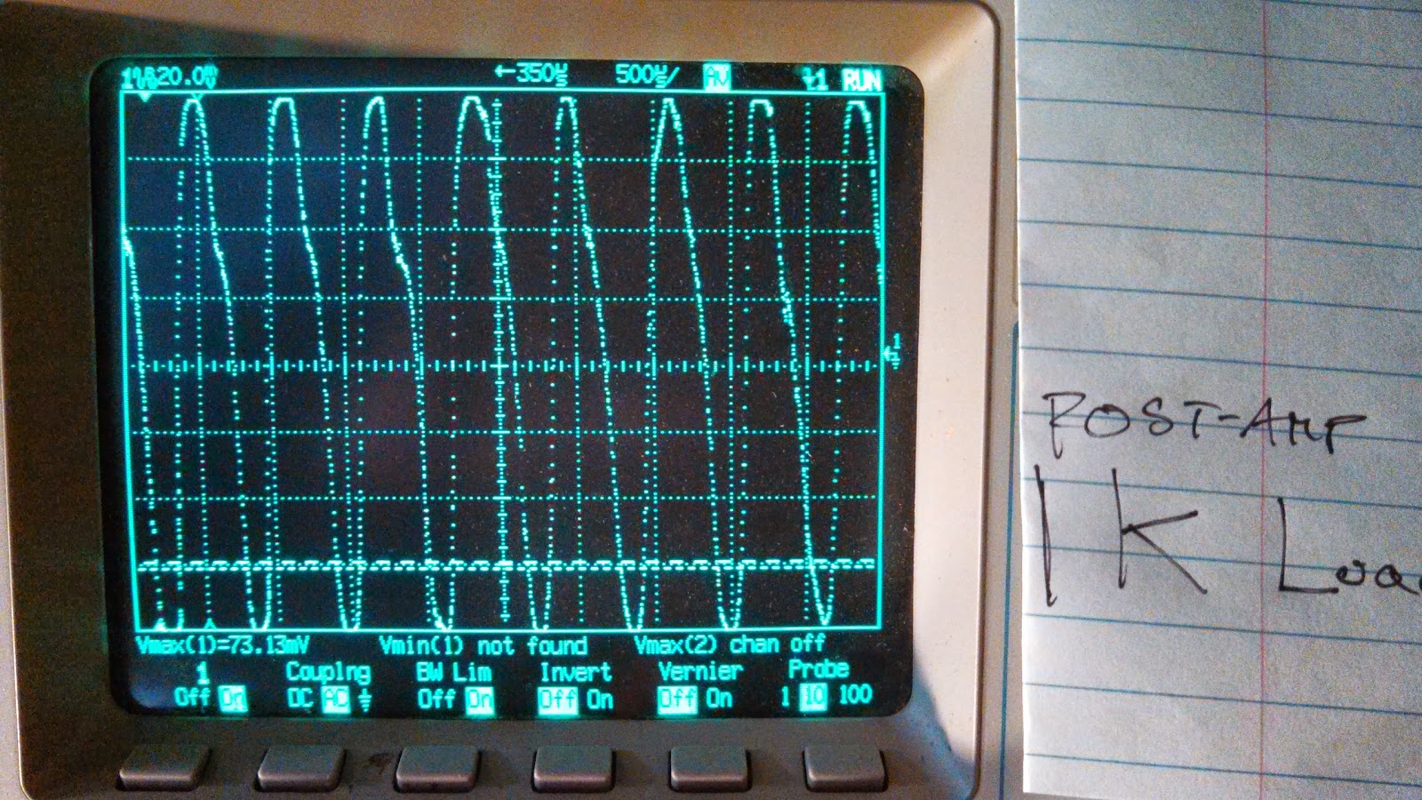
Here is an example of the amplification of a small audio signal. The first image is the audio source driving a 1k load, and the second is the amplifier driving a 1k load while fed by the same source.

It's not without added distortion, but the signal is amplified from about 80mVpp to 160mVpp.
Below are some images of the device itself. Not too pretty, but it works well and was made with only hand tools.
 The current path includes the forward portion of the balance arm and would include the pivot itself if I did bridge it with some thin wire. I expect it would add noise and decrease amplification otherwise.

Below are some waveforms from this thing when it is self-oscillating. There was no input when these were taken.


Completed Curve Tracer Circuit

Long overdue, the more or less final functional circuit of the curve tracer. The phase of the AC inputs is important so that the base bias is stable while the device  under test receives power. I used separate transformers for each. R6/R7 is a potentiometer, as is R8/R9. Vvar is supplied by a variable linear regulator with low dropout.

I used TL712CP comparators for U2 and U1, and IIRC a LM833 dual opamp for U3 and U4.

Below is the circuit as thrown together.
It's not pretty, but it works reliably for any small BJT or FET. Outputs to the oscilloscope are posts on the right side - only the ground connection is clearly visible. The rocker switch at the top switches between PNP and NPN modes by converting U3 and U4 from inverting to noninverting unity amplifiers.