Saturday, July 29, 2017
Monday, February 9, 2015
Homemade Point-Contact Transistor on a Curve Tracer
I recently decided to fool around with another hand made point contact transistor. As in my previous successful attempts, I used the germanium die from an old diode and two points made from phosphor bronze wire. This time I had access to binocular microscope and a proper curve tracer, which made things move along much more easily. The curves shown here were taken without forming the collector, so the gain is low, essentially 1. The base current step size is set at 2µA, and the vertical current display is set to 2µA per division
I tried dabbing some cyanoacrylate glue onto the transistor to hold everything in place before making attempts to form the collector, and while the transistor continued to function as shown at first, after it had hardened it no longer showed useful behavior. I still count this as a success, as it took much less time to get promising results during this attempt than previously. Unfortunately I did not try running the transistor with its attached phase-shift oscillator circuit before operation ceased.
Friday, December 5, 2014
Plasma Speaker
Another old project that I'm just getting around to writing about now. This is a simple plasma speaker, built around a flyback transformer with the core shims removed driven by an arrangement of a TL5001 PWM chip feeding a FAN73832 high and low side N-type MOSFET driver.
It plays pretty well, though the bass tends to distort. A low pass filter on the audio input would not be amiss. The FETs run warm, but not too hot to touch.
Sprucing up an old radio..
I picked up a trashed Crosley 1930's radio at the yearly local antique radio association's swap meet/flea market at the request of a then-girlfriend who wanted to make a gift of it for a close relative. It was in truly terrible shape, so I didn't feel too bad about the possibility of making things worse by being almost completely inexperienced with wood restoration. The speaker was shredded along with the grill cloth, all the electronics were covered in a thick layer of grease and dust and rust, and it had been painted. Repeatedly.
I used a "green" paint stripper with a plastic scraper, and discovered three layers of paint on top of the original finish: glossy black, glossy red, and flat black. I had to remove the original finish as well, which was the most resilient of the coatings.
After many sessions of scraping and scrubbing, the radio was down to bare wood again. After carefully re-gluing some areas of the veneer that had delaminated, I used a number of stains and varnish to make it all pretty again. In the end I did not end up restoring the radio to functionality, as that was less important for my friend. I did still replace the speaker cone and clean up the electronics as much as I could without complete disassembly.
Everyone was pleased with the result in the end, though I know I could have done better. Perhaps there will be a next time..
I used a "green" paint stripper with a plastic scraper, and discovered three layers of paint on top of the original finish: glossy black, glossy red, and flat black. I had to remove the original finish as well, which was the most resilient of the coatings.
After many sessions of scraping and scrubbing, the radio was down to bare wood again. After carefully re-gluing some areas of the veneer that had delaminated, I used a number of stains and varnish to make it all pretty again. In the end I did not end up restoring the radio to functionality, as that was less important for my friend. I did still replace the speaker cone and clean up the electronics as much as I could without complete disassembly.
Everyone was pleased with the result in the end, though I know I could have done better. Perhaps there will be a next time..
Power Supplies for Plate and Filament of Homemade Triode
After revisiting the ongoing project of a crude home made thermionic valve or triode vacuum tube, I decided to dispense with the old Variac-controlled adjustable 60Hz power supplies. I made a new high voltage supply using a simple flyback converter topology, followed by a high voltage linear voltage regulator made from discrete components.
The low voltage supply is still 60Hz, but it is also followed with an adjustable regulator, in this case a LM350, a 3 amp device.
The high voltage is run through a Bogen T725, with a rotary switch selecting an output tap for audio output. This can be seen in the upper left corner. The low and high voltage supplies each have their own electrical cord so I don't have to use both at the same time. I suppose switches would have worked, too.
The power supplies got their first workout in an experiment to see if I could use a silicone rubber gasket in place of the usual RTV for sealing the glass envelope of the triode. It did not work well, but that is in part due to the irregular shape of the sealing surfaces. The filament's life was short and smoky, and I was unable to receive any signals. I completely rebuilt the regenerative radio set for these experiments, so I do hope I didn't miss-wire something. It could also be the fact that I'm attempting to use grid-leak biasing this time around, whereas in the old setup I used a separate variable bias supply for the grid (+/- 17Vdc IIRC).
The low voltage supply is still 60Hz, but it is also followed with an adjustable regulator, in this case a LM350, a 3 amp device.
The high voltage is run through a Bogen T725, with a rotary switch selecting an output tap for audio output. This can be seen in the upper left corner. The low and high voltage supplies each have their own electrical cord so I don't have to use both at the same time. I suppose switches would have worked, too.
The power supplies got their first workout in an experiment to see if I could use a silicone rubber gasket in place of the usual RTV for sealing the glass envelope of the triode. It did not work well, but that is in part due to the irregular shape of the sealing surfaces. The filament's life was short and smoky, and I was unable to receive any signals. I completely rebuilt the regenerative radio set for these experiments, so I do hope I didn't miss-wire something. It could also be the fact that I'm attempting to use grid-leak biasing this time around, whereas in the old setup I used a separate variable bias supply for the grid (+/- 17Vdc IIRC).
Hysteresis/Induction Motor
This is something I built a while ago, but I wanted to describe it in some more detail. It is a simple alternating current motor that spins a thin disk of metal balanced on a sharpened point of graphite.
The circuit applied roughly equal current to each of the coils, phase shifted by 90 degrees. The large AC capacitor provides both phase shift and current limiting to one coil while the other is simply fed through a high wattage resistor. I strung together 12 smaller resistors in series/parallel and even attached heat sinks with thermal grease to get a suitable dissipation power and reasonable resistance of 17.5 ohms.
The two coils act together to produce a rotating magnetic field, as one always precedes the other by 90 degrees. Four coils would produce a much more symmetrical field, but two will do the job. As the steel mason jar lid is magnetized by the increasing field from L1, that part of the steel becomes attracted to the simultaneously falling field from L2, and gets pulled around toward L2. Much the same way, when a rising field near L2 magnetizes the steel that same part of the steel is repelled by the falling field from L1, and pushes the disc from L1 toward L2. This might not be all that is going on, but it suffices for me as an explanation of why this simple induction motor functions at all.
The circuit applied roughly equal current to each of the coils, phase shifted by 90 degrees. The large AC capacitor provides both phase shift and current limiting to one coil while the other is simply fed through a high wattage resistor. I strung together 12 smaller resistors in series/parallel and even attached heat sinks with thermal grease to get a suitable dissipation power and reasonable resistance of 17.5 ohms.
The two coils act together to produce a rotating magnetic field, as one always precedes the other by 90 degrees. Four coils would produce a much more symmetrical field, but two will do the job. As the steel mason jar lid is magnetized by the increasing field from L1, that part of the steel becomes attracted to the simultaneously falling field from L2, and gets pulled around toward L2. Much the same way, when a rising field near L2 magnetizes the steel that same part of the steel is repelled by the falling field from L1, and pushes the disc from L1 toward L2. This might not be all that is going on, but it suffices for me as an explanation of why this simple induction motor functions at all.
Saturday, November 30, 2013
Piezo-driven unstable carbon contact amplifier
This is my take on the "balance beam amplifier" from H.P. Friedrich's book, "Instruments of Amplification." This is essentially a relay mechanically biased to partway between on and off, with a soft contact material that varies its resistance with pressure: carbon. Way back in the day, circa 1910, such a device would have been driven electromagnetically. I attempted such a design a few years ago without much luck. This time around I happened upon the very good idea of using a piezoelectric disc in place of a more complicated set of coils and magnets. The efficiency of the disc is very high, and has a very high impedance which matches well to crystal radios made with high count litz wire. The only better possible driver would be a sound powered phone aka balanced armature speaker, and I may try that in the future for even better performance.
The most efficient piezo disc I could find at Radio Shack is the driving element in this design. A 100k resistor is connected to it in parallel, and any weak audio source (such as that from a robust crystal radio) is enough to drive it. I took pieces of the carbon rod from the center of a carbon-zinc ("Heavy Duty") D-cell battery to make the amplifying relay contacts. One piece is secured to the center of the piezo disc and the other is on the end of an adjustable balance arm. Counterweights on the other end of the arm adjust the resting pressure between the contacts.
Two D-cell batteries in series provide power - this runs to one carbon, across the unstable contact to the other carbon, through a 50 ohm winding on an audio transformer, and back to the battery. As the vibrations from the piezo disc vary the resistance between the carbons, the current through the transformer varies and is output from another winding to a sound powered phone.
This thing DEFINITELY amplifies! On a strong local station the output can be uncomfortably loud. Adjustment is very sensitive, and it often will take off in self-oscillation.
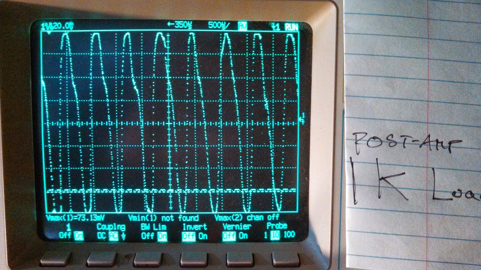
Here is an example of the amplification of a small audio signal. The first image is the audio source driving a 1k load, and the second is the amplifier driving a 1k load while fed by the same source.
It's not without added distortion, but the signal is amplified from about 80mVpp to 160mVpp.
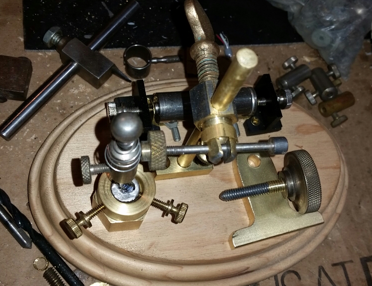
Below are some images of the device itself. Not too pretty, but it works well and was made with only hand tools.
The current path includes the forward portion of the balance arm and would include the pivot itself if I did bridge it with some thin wire. I expect it would add noise and decrease amplification otherwise.
Below are some waveforms from this thing when it is self-oscillating. There was no input when these were taken.
The most efficient piezo disc I could find at Radio Shack is the driving element in this design. A 100k resistor is connected to it in parallel, and any weak audio source (such as that from a robust crystal radio) is enough to drive it. I took pieces of the carbon rod from the center of a carbon-zinc ("Heavy Duty") D-cell battery to make the amplifying relay contacts. One piece is secured to the center of the piezo disc and the other is on the end of an adjustable balance arm. Counterweights on the other end of the arm adjust the resting pressure between the contacts.
Two D-cell batteries in series provide power - this runs to one carbon, across the unstable contact to the other carbon, through a 50 ohm winding on an audio transformer, and back to the battery. As the vibrations from the piezo disc vary the resistance between the carbons, the current through the transformer varies and is output from another winding to a sound powered phone.
This thing DEFINITELY amplifies! On a strong local station the output can be uncomfortably loud. Adjustment is very sensitive, and it often will take off in self-oscillation.
Here is an example of the amplification of a small audio signal. The first image is the audio source driving a 1k load, and the second is the amplifier driving a 1k load while fed by the same source.
It's not without added distortion, but the signal is amplified from about 80mVpp to 160mVpp.
Below are some images of the device itself. Not too pretty, but it works well and was made with only hand tools.
The current path includes the forward portion of the balance arm and would include the pivot itself if I did bridge it with some thin wire. I expect it would add noise and decrease amplification otherwise.
Below are some waveforms from this thing when it is self-oscillating. There was no input when these were taken.
Subscribe to:
Posts (Atom)